|
|
service |
|
||||
|
|
and |
|
||||
|
|
Maintenance |
|
||||
|
instructions |
|
|||||
|
MODEL 12 HYDROSTATICTRANSAXLE |
Used on
Models 197 198 1476 |
|
||||
|
|
|
|
||||
|
|
|
|||||
|
|
||||||
|
|
PORT WASHINGTON,
WISCONSIN, USA
|
|
||||


Index
HUSKY HYDROSTATIC TRANSMISSION TABLE OF CONTENTS
Page
Description 1
Marshallmatic Hydrostatic Flow Diagram 2
Operating of Vehicle
3
Fonction of the Tractor Transmission Lever 3
General Maintenance
4
Troubleshooting
4
Removal of Complete Transaxle Assembly from
Tractor 5
Installation of Complete Transaxle 6
Travel-Pedal Dampener
6
Removal of Hydrostatic Package from Transaxle 7
Alternate Hydrostatic Package Removal Procedure 9
Installation of the Hydrostatic Package 9
Rear Axle Disassembly
il
Differential Disassembly 12
Differential Bevel Gear Backlash 12
Needle Bearing Replacement 12
Disassembly of Parking Pawl 13
Disassembly of Unloader Valve Button Assembly 13
Field Removal and Installation of Axle Seal 13
Parts List 13
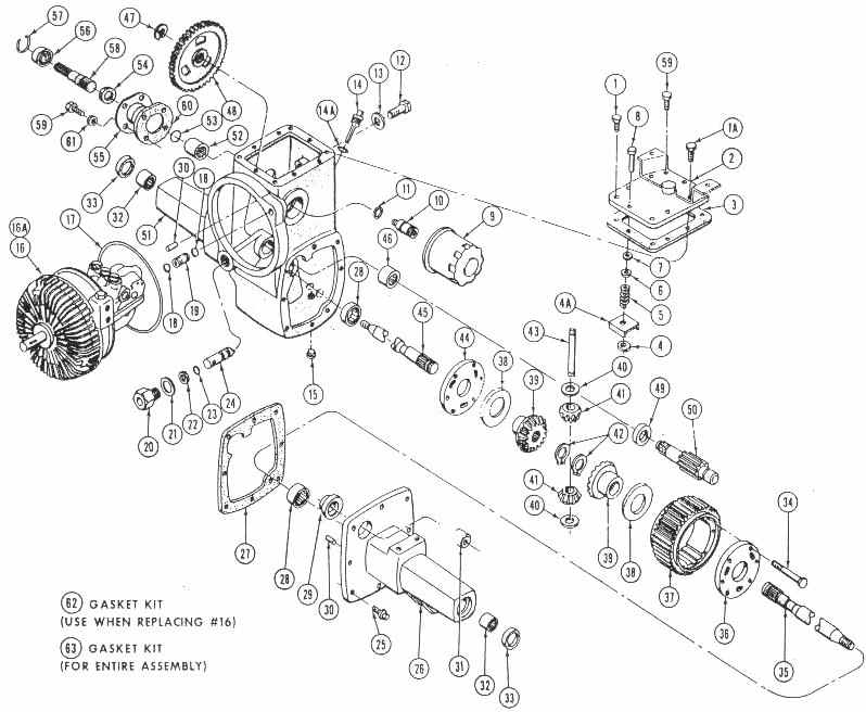
Hydrostatic Exploded View 14
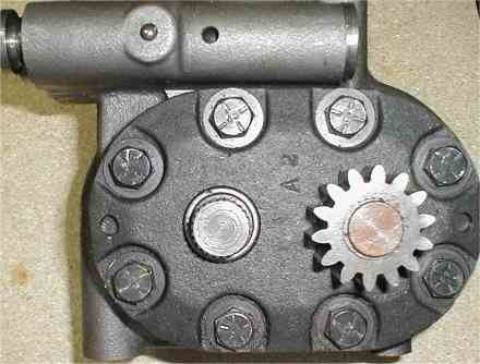
NEUTRAL VALVE
COVER BOLTS
11 . . . . . . LOCATING BOLT
OIL FILTER
AP
)RAI (NOT
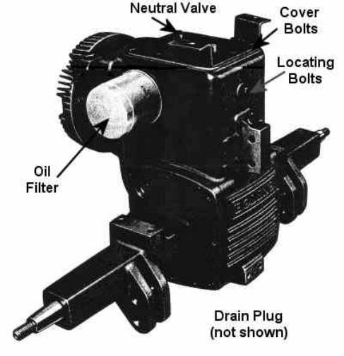
Figure 1
|
DESCRIPTION |
automatically as the drawbar load of the tractor
increases and decreases. |
|
The Husky Model 12 hydrostatic transmission converts
mechanical energy at the input shaft into pressure in a nearly incompressible
working fluid, and then reconverts it into mechanical energy at the output
shaft. The purpose of this transformation is to provide a means of varying
the output torque, speed and direction, with a constant input speed. In
operation the pressure within the hydrostatic transmission is variable and
will increase and decrease. |
The hydrostatic transmission is composed of three
major parts - a variable displacement
radial-piston pump; a fixed displacement gear motor; a system of valves
located between the pump and motor. By varying the displacement of the pump
an infinite number of speeds are available within a range of 8 miles per hour
in forward and 4 miles per hour in reverse at full engine R.P.M. |
|
|
|
Marshallmatic
Hydrostatic
Flow
Diagram
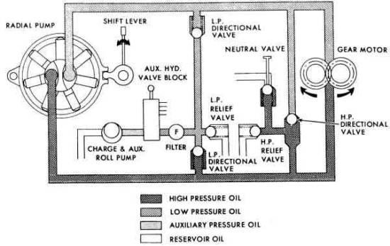
Figure 2
FLOW DIAGRAM
|
|
|
In operation, the pump produces a flow of oil
through internal channeling forming a closed loop between the pump and the
motor. The oil flow produced by the pump is represented on the chart by the
checked area and that flow returning from the motor to the pump is the crossed
area. Vehicle speed regulation is achieved by changing the
oil delivery of the variable displacement pump. When the lever is moved in
the forward (clockwise) direction, the cam ring is moved off center and oil
immediately begins to flow through the circuit. Moving the position of the
speed control pedal in the forward direction will vary the flow of oil, which
in turn will vary the speed of the tractor. When the speed control pedal is
moved in the reverse direction (counter clockwise), the flow of oil is
reversed and the tractor will also reverse its direction. It should be kept
in mind that since the circuit is a closed-loop and that oil is relatively
incompressible, whatever flow reaches the fixed displacement motor will immediately
be transmitted into a certain speed, depending on the volume and direction of
the flow. In order to better understand the circuit, refer to
the white channeling on the flow diagram at the charge |
or auxiliary roll-pump. This pump serves as the
inlet for the hydrostatic transmission circuit and distributes the reservoir
oil in the transaxle housing. The roll pump or charge pump performs three
functions: 1. Maintains flow and pressure in auxiliary
hydraulic circuit, 2. Maintains some pressure on the low-pressure side
of the hydrostatic circuit so as to supercharge the variable displacement
pump and,. 3. Supplies oil lost due to internal leakage in the
hydrostatic circuit. Following the circuit from this point, the dotted
channeling denotes the auxiliary pressure, established by a valve in the
auxiliary hydraulic valve block. Next, the oil flows through a filter which
removes particles of dirt and other foreign matter. The oil then flows to a
pair of directional check valves and the low pressure relief valve. At this
point there is more oil available than is needed to make up losses, so oil
must circulate past the low pressure relief valve back into the reservoir.
The directional valves are pressure dependent and the lower directional valve
on the flow diagram is closed |
|
|
|
due to
the high pressure oil behind it, therefore, the make-up oil enters the upper
or low-pressure side of the circuit. In reverse, the make-up oil enters
through the lower directional valve. All
hydraulic circuits must be protected by a high pressure relief valve, which
in this case is located in the circuit after the high pressure directional
valve. Since a directional valve is used here, only one high pressure relief
valve is required to protect the circuit whether it is operating in forward
or reverse direction. Finally, there is a neutral valve which is actuated
by the tractor transmission lever. In order to achieve neutral or "free
wheeling", the oil is "dumped" back into the reservoir,
bypassing the gear motor. This makes it possible to move the tractor when in
NEUTRAL while the engine is not operating. With the selector lever in PARK,
the neutral valve is also open. When the selector lever is in DRIVE, the neutral
valve is allowed to close thus completing the "closed loop' OPERATING
OF VEHICLE
For
optimum control and power, the Husky hydrostatic tractor should be operated
at constant FULLTHROTTLE ENGINE SPEED. Complete control of the vehicle is
accomplished through the use of the travel pedal. When operating the vehicle
under varying load conditions, there will be a noticeable change in ground
speed. It should be noted that when ground speed is reduced due to greatly
increased loads, the speed control pedal should be directed toward the
neutral position in order to increase the torque to the rear wheels. For
example, if the engine starts to "lug" down while attempting to
maintain a given speed when encountering a hill or other increased load, it
is important to move the travel pedal toward neutral rather than toward full
speed. This is the same as shifting down to a lower gear with a typical
mechanical transmission. |
Prolonged lugging or full travel-pedal position that
demands maximum engine output will raise engine and hydrostatic oil
temperatures. If the vehicle has been performing under the previously
mentioned condition, allow it to operate at a lower ground speed (lighter
load but at FULL ENGINE R.P.M.), then normal operating temperatures will
again be established. 160°-170°F. is the normal operating temperature
of the hydrostatic. These temperatures will feel hot "to the
touch". IMPORTANT
OPERATOR MUST KEEP FOOT ON THE
TRAVEL-PEDAL FOR MAXIMUM CONTROL OF TRACTOR. MOVING TRAVEL-PEDAL MANUALLY TO
NEUTRAL OR BEYOND TO OBTAIN DESIRED DECELERATION BY MEANS OF DYNAMIC BRAKING
IS THE METHOD INTENDED IN HYDROSTATIC DESIGN. FUNCTION OF THE BOLENS TRACTOR TRANSMISSION LEVER
PARK -
NEUTRAL - DRIVE The Husky Model 12 hydrostatic transmission has a
closed hydraulic circuit, therefore, the vehicle cannot be pushed unless an
oil by-pass exists. This oil by-pass operates in conjunction with the
transmission lever as described above. 1. When the transmission lever is in the DRIVE or
closed position, the vehicle is operated entirely with the speed control
pedal. When the transmission lever is in the NEUTRAL or center position, the
vehicle may be pushed by hand; whether or not the engine is running. 2. When in the PARK or rear position, the vehicle
should not be pushed under any circumstances because of possible damage to
the parking lock. NOTE The transmission lever should never be placed in the
PARK position when the vehicle is moving. CAUTION Do not
tow or free wheel over 8 MPH. |
|
GENERAL
MAINTENANCE OIL LEVELThe oil level should be checked after every eight
hours of operation and should always be maintained between the add and full
lines on the dipstick. Allow the engine to idle for a few minutes before
checking the oil level. If it is necessary to add oil, only type A
transmission fluid or special oil available from Bolens should be used. IMPORTANT
ALWAYS WATCH FOR OIL LEAKS AT HOSES, SEALS AND FITTINGS. LOW LEVEL OR INADEQUATE OIL WILL RESULT IN PERMANENT DAMAGE TO HYDRAULIC SYSTEM. OIL FILTER (Fig. 1) The Husky Model 12 transaxle is equipped with a
replaceable oil filter which can be removed by turning it counter clockwise.
Oil filter change: Home Owners: Once a year or 300 hours. Industrial or Commercial: Once every three months or
whenever dipstick check indicates dirty oil. COOLINGTo maintain proper cooling, the transaxle exterior
should be kept free of dirt, oil and grass, particularly the finned area
behind the fan. NOTE
Numbers in parentheses ( ) in text correspond to
numbers shown on exploded parts view, page 14.
|
TROUBLESHOOTING TRACTOR PERFORMANCE CHECK OF ENGINE & TRANSMISSION To perform a temporary power check, carefully
"square off" or align both front wheels evenly against a solid
wall. With both front tires firmly against this wall, pull throttle control
knob out 3/4 to full, and gradually depress speed control pedal applying load
slowly until tires spin. NOTE
Tires normally will spin on dry concrete or macadam
with the standard 27-8:50 x 15 tires with no additional rear-end loading
except the operator. Terra tires, 26-12 x 12, will be more difficult to spin,
especially on rough dry concrete. IMPORTANTTHIS IS
ONLY A TEMPORARY PROCEDURE TO AID IN QUICKLY CHECKING OUT GENERAL ENGINE AND
TRANSAXLE PERFORMANCE. HOWEVER, A FEW TRIES ARE USUALLY ADEQUATE TO ALLOW AN
EXPERIENCED MECHANIC TO OBSERVE GENERAL ENGINE PERFORMANCE, SUCH AS ENGINE
MISS, CARBURETOR ADJUSTMENTS, GOVERNOR ACTION, ETC. If engine performance appears to be normal and a
thorough inspection of loose linkage connections, leaks, adjustments, etc.,
has been carried out, then proceed as follows. 1.
On 1250 tractors only, remove spring from speed hold pedal. 2. Remove complete fender assembly (two capscrews,
one on either side, holding front fender to frame and two bolts under the
seat). Disconnect tail light wire. TRANSAXLE DRIVE-LINE FAN NOW EXPOSED. IF AN ATTEMPT IS MADE TO TEMPORARILY RUN THE ENGINE, BE EVER AWARE OF SPINNING FAN BLADES WHILE ENGINE IS RUNNING. 3.
Observe all mechanical linkage; free up, tighten or correct if necessary. 4. Recheck all hydraulic connections and seals for
leakage. LOSS OF POWER: A.
Drive-Neutral-Park control rod not adjusted properly to unloader actuator
(located on top of transmission cover). B.
Oil level in transmission below level. C.
Defective O-ring (11). D.
Defective hydrostatic package (16). |
|
E.
Foot brake adjustment too tight. F.
Unloader valve sticking (should return freely) (8). G.
Defective unloader actuator. LOSS
OF OIL: Defective
or damaged parts: A.
O-Ring (17) B.
Cover Gasket (3) C.
Unloader Valve Button Gasket (7) D.
Parking Pawl Gasket or O-Rings (21, 22, 23) E.
O-Ring (18) F.
Axle Oil Seal (33) G.
Gasket (27) H. Service Brake Shaft Seal (54) or Gasket (60) NOTE To replace O-Rings (17 and 18), follow instructions
on page 9. I.
Defective Lift Valve J.
Leaking Lift Cylinder K. Defective or loose hydraulic lift hoses and
fittings LIFT VALVE AND CYLINDER WILL NOT LIFT OR HOLD A.
Defective or leaking lift valve. B.
Leaking cylinder, C.
Hydraulic lift hoses crossed at transmission outlet ports. D.
Defective hydraulic hoses. Plugged or kinked. E. Defective charge pump in Hydrostatic, TRAVEL PEDAL FLUTTERAfter usage the speed control pedal may develop a
pronounced flutter. This could occur with engine at fast idle: - transmission lever in DRIVE; -and foot removed from
speed control pedal. The DAMPENER adjustment described on Page 6, Fig. 5 will again produce desired action. REMOVAL OF COMPLETE TRANSAXLE ASSEMBLY FROM TRACTOR Cleanliness is the first order. Clean the
transmission prior to disassembly. 1. On 1250 tractors only, remove return spring from
speed hold pedal. 2. Remove complete fender assembly (two capscrews,
one on either side, holding front fender to frame and two boltsunder the
seat). Disconnect tail-light wire. |
3.
Drain oil - the oil plug (15) is located at the bottom of the transmission.
After transaxle is drained, reinstall plug. 4.
Remove brake rod return spring from seat bracket. 5.
Remove seat bracket, two bolts per side. 6.
Remove oil filter from transaxle (9). 7. Remove hydraulic lift lines and tie loose ends up
to steering wheel. NOTE
Temporarily mark either top or bottom hydraulic lift
hoses (so they are not accidentally crossed at reassembly). Lift ram will not
operate if hoses are crossed. 8.
Remove the upper and lower hydraulic elbow fittings from the hydrostatic
package. 9.
Remove hydraulic unloader valve actuator assembly located on top side of
transaxle cover by removing two capscrews holding casting over unloader valve
cap. Pivot the unloader valve actuator and rod assembly and lean forward
against steering column. 10.
Remove two bolts (right side) to remove complete brake assembly and disc. 11.
Remove cotter pin and clevis pin from control arm interlock plate; remove
cotter key from parking pawl linkage at transmission end - allow loose end to
swing down. 12.
Slightly raise and safely block up tractor main frame just forward of
transaxle so tires barely leave floor. 13. Remove the four capscrews (two per side) that
hold transaxle to main frame. CAUTIONCAREFULLY BALANCE TRANSAXLE WHILE REMOVING MAIN
FRAME CAPSCREWS, TO AVOID ACCIDENTAL INJURY OR TRANSAXLE DAMAGE. ROLL
TRANSAXLE OUT OF TRACTOR FRAME. WHEN REMOVING THE TRANSAXLE FROM THE FRAME,
THE DRIVE-LINE WILL SLIP OFF THE TRANSMISSION INPUT SHAFT. NOTEDo not allow drive-shaft to drop free. Fan blade
damage could result. 14.
Remove woodruff key from transmission input shaft; wheels, hubs and drive
keys from axles. 15. Remove hex nut, lock washer and washer holding
control-arm to control shaft, Figure 3. With a small gear puller remove
control arm from shaft. Remove control arm interlock plate. NOTEIf hydrostatic is the older model, the control arm
is held on with a drive cross pin. (See insert Figure 3.) |
|
Use a 3/16" drift punch to drive out pin.
Locate punch on pin through slot of the control-arm and drive out pin toward
rear of transaxle assembly. INSTALLATION OF COMPLETE TRANSAXLE
IMPORTANT "CLEANLINESS IS THE FIRST ORDER! ALWAYS AVOID
DUST, GRIT OR OTHER CONTAMINATION WHEN WORKING WITH HYDRAULIC CONNECTIONS. INSTALLATION1.
Install hubs, keys and wheels on replacement transaxle. 2.
Install woodruff key into keyway of transmission input shaft. 3.
Temporarily remove new oil filter from replacement transaxle to avoid damage. 4.
Reinstall linkage on transaxle control shaft. 5.
Install replacement transaxle. Grease input shaft, and carefully guide input
shaft into drive line. Bolt replacement transaxle to tractor main-frame with
the four capscrews. (TIGHTEN TO 60 FOOT POUNDS.) 6. Install drive keys to axles - install hubs and
wheels. NOTE Liberally apply grease to rubber O-ring on filter. 7.
Reinstall the new filter by grasping with both hands and tighten securely. 8.
Reinstall parking pawl linkage by inserting link into pawl cross hole and
insert cotter pin (Fig. 3). 9.
Grease spline and reinstall disc brake assembly. 10.
Reinstall elbows into auxiliary valve body as shown on Figure 3. 11. Reinstall hydraulic-lift hoses. NOTE Upper and lower hoses must be reinstalled in their
original position. 12.
Install seat bracket. 13. Reassemble foot brake and return spring to brake
rod loop provided; anchor other end of spring to hole provided in seat
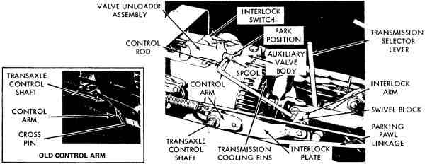
bracket. LINKAGE ADJUSTMENT (Refer to Fig. 3.) 1.
Reinstall hydraulic unloader-valve assembly with two bolts onto transaxle
cover. 2.
Turn the two jam-nuts on control rod away from swivel block. Place
transmission lever in PARK position so parking pawl is fully meshed in
bull-gear. 3. Push spool of the neutral valve unloader assembly
back into the PARK detent position (front detent groove inside casting under
the spring loaded ball). |
4.
Securely tighten jam-nuts against swivel block. 5.
Cross-check jam-nut adjustment by placing Selector Lever in NEUTRAL position. 6. Push tractor forward and back to determine if
tractor free-wheels. Then place transmission lever into DRIVE. Activate foot
pedal, and observe if slot pin in transaxle control linkage moves freely into
upper and lower slot of interlock plate. If interference is evident, readjust
jam-nuts slightly to eliminate "interlock vs. slot-pin"
interference. TRAVEL-PEDAL DAMPENER (REFER TO FIGURE 5) The Model 12 Bolens Husky is equipped with a
Travel-Pedal Dampener which consists of the travelpedal control-rod pivot
block #171-9041, Reference A, and two bowed washers #171-9453, Reference B,
mounted on the hydrostatic control linkage located on the right-hand side of
transaxle. Note the position of the two special bowed washers as viewed from
the rear. If washers are not positioned in the manner shown at Reference B in
the drawing, correct before attempting adjustments outlined below.
Figure 5
When the Travel-Pedal Dampener is adjusted too
tight, the travel-pedal will return toward neutral very slowly or not at all,
thus a creeping action will result. If pedal action appears too stiff,
locknut C and capscrew D should be loosened to readjust pedal dampener to
obtain just a slight resistance when moving travel-pedal by hand. Relock
capscrew D with locknut C while holding capscrew D in that position. If pedal action is too loose, which may occur after
some vehicle usage, a pedal flutter may become apparent. To adjust, loosen
locknut C and tighten capscrew D one flat at a time (1/6 of a turn) until
flutter is eliminated; then relock capscrew D with locknut C while holding
capscrew D in that position. |
|
FENDER INSTALLATION1.
Place selector lever in NEUTRAL (Fig. 4). 2.
Reinstall seat and fender assembly. Tighten all four fender bolts securely. 3.
Reconnect tail-light wire. 4. Refill transaxle with approximately 8 quarts of
Texamatic No. 1846-6159, Bolens Part No. 171-9650. NOTE Oil
level check can be disregarded at this point. 5.
With selector lever in PARK, run engine at half to three quarter throttle,
purge air from hydraulic lift cylinder, by cycling lift cylinder until ram
action is smooth. 6.
Recheck all hydraulic connections and oil filter for leaks. 7.
Idle engine, then add additional hydraulic oil up to plug level (usually
1-1/2 to 2 quarts required). NOTEOil level can not be accurately checked if the
tractor has been sitting for any length of time. (Oil may run out if dipstick
is removed when engine is not running.) |
8.
Place selector lever in PARK position; run engine for at least two minutes.
This procedure will again allow the oil to refill all internal hydraulic
circuits. 9.
With engine idling remove dipstick to observe if oil level is up to bottom of
threads of filler plug hole. IMPORTANT
BEFORE CHECKING OIL ALWAYS THOROUGHLY CLEAN AREA AROUND DIPSTICK PLUG TO AVOID DIRT OR OTHER CONTAMINATION FROM ENTERING TRANSAXLE. 10.
Normal operating temperature of oil is approximately 100° F above ambient temperature. An oil
level check when transmission is hot will read overfull. Always idle unit for
a short period to allow transaxle to cool down to obtain the best oil level
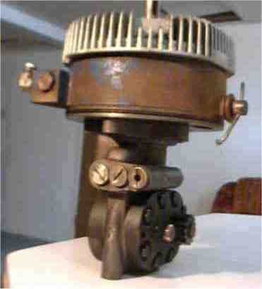
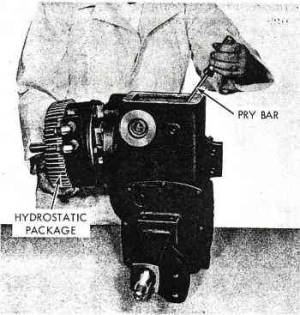
reading. REMOVAL OF HYDROSTATIC PACKAGE FROM TRANSAXLENOTE Removal
of the hydrostatic package (16) from the transaxle can be accomplished
without removing the complete transaxle from the frame of the tractor.
Hydrostatic package will be handled as a factory exchange only. Piece parts
other than those listed on pages 13 and 15 are not available as separate
repair parts because of select fits required. 1. Follow procedures on page 5 using steps 1 thru 11
only. |
|
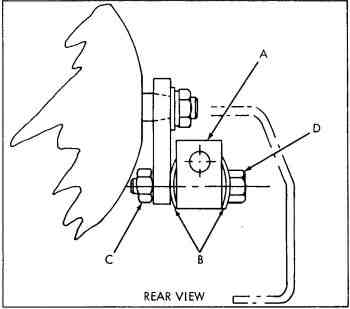
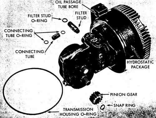
Figure 6
|
2.
Loosen set screw, remove drive-line positioner (bolt with stop nut) from
front joint at engine; move drive-line toward front so the rear joint clears
the end of transmission shaft. Then completely remove drive-line assembly by
pulling complete drive-line down and off the engine crankshaft. AVOID BENDING
FAN BLADES ON DRIVE-LINE.
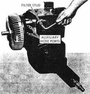
Figure 7
3. Refer to Figures 7 and 17, and remove filter stud
using a wide blade screwdriver - on new design stud, use 3/8" Allen
wrench to remove stud. NOTEO-Ring should be loose on filter stud.
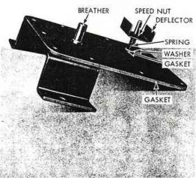
Figure 8
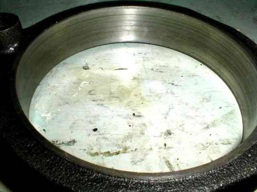
4. Remove cover bolts (1, 1A, 59), lift off cover
bracket (earlier style bracket welded to cover), remove cover sub-assembly
and cover gasket (2 and 3) (Fig. 8 and 17). |
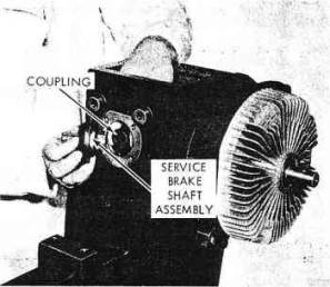
Figure 9
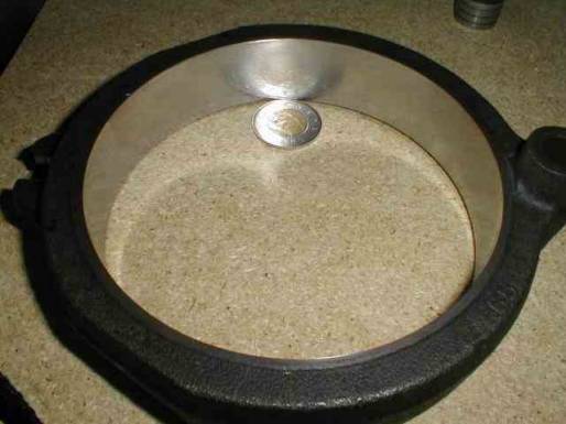
5.
Remove brake flange, four bolts and gasket (59 and 61), tap lightly and pull
out brake flange assembly (55). Observe to see that brake coupling (52) is
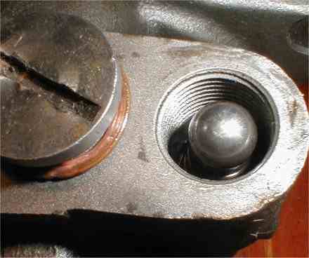
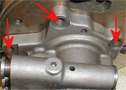
also removed, (Fig. 9 and 17). 6. Remove locating bolt (12) and gasket (13) (Fig. 1
and 17).
Figure 10
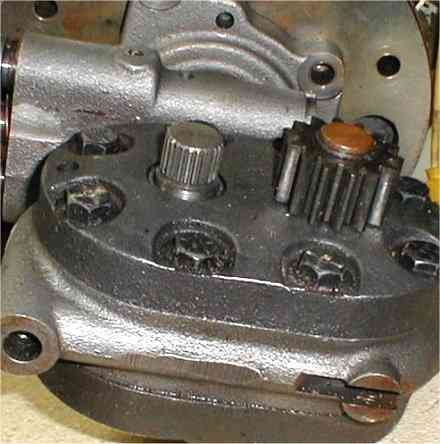
7. Firmly hold input-shaft (or lower fin area) of
hydrostatic transmission with right hand -use screwdriver and wedge lightly
between inside of transmission housing and rear surface of hydraulic motor
block casting - lightly pry transmission forward. Then use both hands to move
hydrostatic package out of transaxle housing, using a rocking motion (Fig.
10). |
|
ALTERNATE HYDROSTATIC PACKAGE REMOVAL PROCEDURE Removal
of hydrostatic package from transaxle (16) - Page 8. If
universal joint set-screw at engine end of drive line cannot be loosened, the
following step can be taken to remove transmission. (Follow all steps except
step 2.) IMPORTANT
REPLACE STEP 2 WITH THE FOLLOWING INSTRUCTIONS. Remove
three of the four cap screws holding transaxle to main-frame of tractor. CAUTION
Support
the transaxle by holding the cover bracket (transaxle is front-end-heavy and
will tip forward if not held manually in original plane) while removing
fourth cap screw. Carefully
push main-frame forward very slowly while holding transaxle stationary
(wheels still on transaxle) until rear hole of frame is indexed with front
hole of transaxle. Again insert one cap screw and tighten.
Figure 11
|
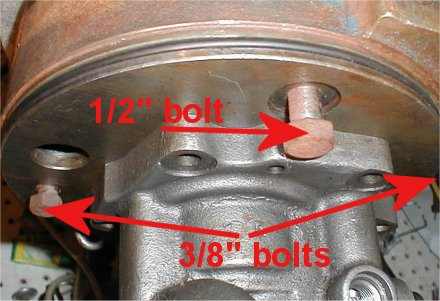
With
standard tires - remove 3 bolts and loosen the right rear to allow unit to be
pivoted to the left. With large tires, bolt as spelled out above. NOTE
The
drive line will slide off the transaxle input shaft. Then the hydrostatic
package can be removed from the transaxle housing. For
installation, reverse above procedure. INSTALLATION OF THE HYDROSTATIC PACKAGE Whenever
replacing hydrostatic package (16), use Gasket Kit (62). 1.
Reinstall linkages on transaxle control shaft. 2.
Before installing .hydrostatic package, inspect O-ring (17) for cuts, nicks
and etc. Carefully install O-ring (17) in groove -in hydrostatic housing. Be
sure O-ring is not twisted. If O-ring is twisted insert small, smooth, blunt
rod between O-ring and groove and run around housing slowly. This will allow
O-ring to untwist. Liberally coat O-ring with heavy oil or grease to prevent
damage in installation. 3.
Check oil passage tube (19) and O-rings (18) (must be free of cuts, nicks and
etc). Install O-ring in grooves in oil passage tube (19) again checking to be
sure O-rings are not twisted. Coat O-rings with heavy oil or grease to
prevent damage in installation. Insert tube into hydrostatic bore shown in
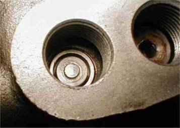
Figure 6. 4.
Carefully insert hydrostatic package partially into main housing (51). NOTE
A
slot located on the back end of the motor of the hydrostatic package should
be centered on the dowel pin (Fig. 11) of the main housing. This mating can
be observed through the top cover access-hole. 5.
With the slot in line with the dowel pin, carefully insert the package (16)
observing the O-ring (17). IMPORTANT
THIS RING SHOULD NOT BE PINCHED OR CUT
AT ASSEMBLY. DURING THE ASSEMBLY, CAUTION SHOULD ALSO BE TAKEN IN ENTERING
THE OIL TUBE (19) WITH MATING BORE IN MAIN HOUSING (51). COMPLETE INSERTION
OF THE HYDROSTATIC PACKAGE INTO THE MAIN HOUSING CAN BE ATTAINED BY PLACING A
FLAT TOOL BETWEEN THE RECESS LOCATED IN FRONT OF THE THREE ACCESS CAPS ON THE
MOTOR BLOCK AND THE FRONT TOP COVER FLANGE AND WEDGING INTO PLACE. |
|
|
6.
Before inserting special positioner bolt with gasket (12 and 13), observe to
see if the dowel pin (Fig. 11) in the transaxle housing is in line with
hydrostatic motor casting slot. If not, gently move (using rocking motion) in
place. Insert bolt (12) and start thread engagement by hand. NOTE
The
pinion gear hydrostatic motor-shaft will mesh automatically with bull gear
(Fig. 11) when special 1/211 positioner bolt (12) is securely tightened.
Torque to 40 ft. lbs. 7.
Reinstall filter stud (10) and filter (9). 8.
Insert spline coupling (52) onto splined shaft of brake flange assembly (55)
with gasket (60), insert this assembly on spline shaft of the motor. Tighten
securely with four bolts and gaskets (59 and 61). 9.
Reinstall parking pawl linkage by inserting link and cotter pin. 10.
Reinstall disc brake assembly. 11.
Reinstall elbows into auxiliary valve body located on left front side of
transaxle. 12.
Reinstall hydraulic-lift hoses. Upper and lower hoses must be reinstalled in
their original position. NOTE
Upper
hose goes to left hand side of valve and lower hose goes to right hand side
of valve. 13.
Reinstall keys and drive-line after lubricating both shafts. |
14.
Insert special positioner bolt through front joint and engine crankshaft,
tighten securely. 15.
Reinstall hitch and rear seat bracket. 16.
Reassemble foot-brake and return spring to brake rod ear provided; other end
of spring to hole provided in seat bracket. TRAVEL
PEDAL LINKAGE ADJUSTMENT (Refer
to Fig. 3) With
the selector lever in its DRIVE position, all transmission linkage should
move freely. 1.
Reinstall hydraulic unloader valve assembly with two bolts onto transaxle
cover. 2.
Turn the two jam-nuts on control rod away from swivel block, then place
selector lever in PARK position. 3.
Push spool of unloader assembly back into the PARK detent position. (Front
detent groove inside casting.) 4.
Adjust the two jam-nuts on swivel block of selector arm at that position.
Cross-check jam-nut adjustment by placing selector lever in NEUTRAL position.
Then push tractor forward and back to determine if tractor free-wheels
freely. 5.
Place lever into DRIVE. Then by activating foot pedal, observe if pin in
transaxle control linkage moves freely into upper and lower slot of interlock
plate. If interference is evident, readjust jam-nuts to eliminate
"interlock vs. slot-pin"interference. |
|
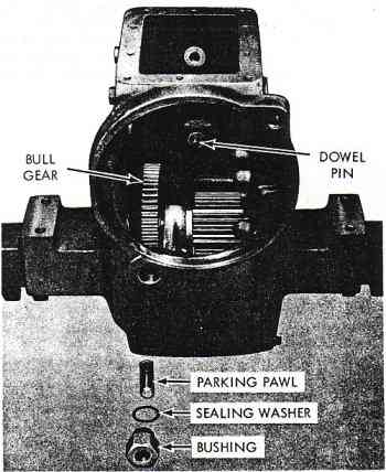
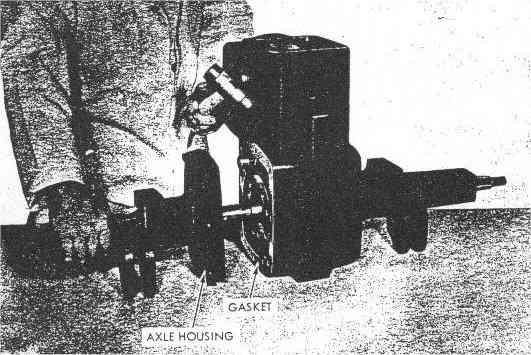
Figure 12
|
6.
Place selector lever in NEUTRAL; reinstall seat and fender assembly. Tighten
all four bolts securely. 7.
Reconnect tail-light wire. 8.
Refill transaxle with approximately eight quarts of Texamatic No. 1846-6159,
Bolens Part No. 1719650. Oil level check can be disregarded at this point. 9.
Run engine at half to three quarter throttle, purge air from hydraulic lift
cylinder, by cycling lift cylinder until ram action is smooth. 10.
Check all hydraulic connections and filter for leaks. 11.
Idle engine, then add additional hydraulic oil up to plug level. (Usually
1-1/2 to 2 quarts required.) NOTE
Oil level. Seepage 7. REAR AXLE
DISASSEMBLY
1.
Remove eight axle housing bolts (25) securing axle housing to transaxle
housing. 2.
Tap axle housing lightly with plastic or rawhide mallet to loosen the seal.
Slide axle housing off axle carefully to prevent damage to oil seals (Fig.
12). 3.
Remove gasket (27) and clean casting surfaces (Figs. 12 and 17).
Figure 13
|
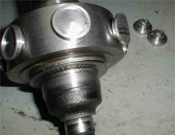
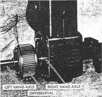
4.
Carefully slide differential assembly from transaxle housing to prevent
damage to oil seals (Fig. 13). NOTE
It
is not necessary to remove hydrostatic package from the transaxle housing to
accomplish differential removal. 5.
In order to accomplish removal of remaining gears, it is necessary to remove
the hydrostatic package. 6.
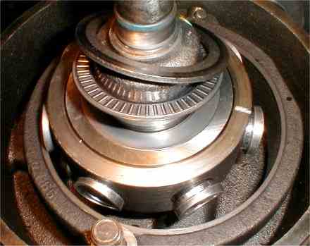
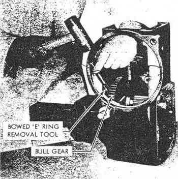
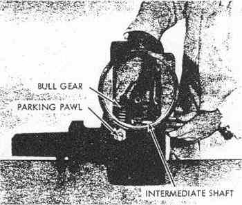
Refer to Figures 14, 15 and 17, and remove bowed E-ring (47). While holding
bull gear (48), slide intermediate shaft (50) and spacer (49) out of
transaxle housing.
Figure 14
Figure 15 |
DIFFERENTIAL DISASSEMBLY 7.
Remove six bolts (34) from the differential assembly. Tap either axle shaft
lightly until either axle assembly (right or left) is separated from the ring
gear (37) and remove remaining axle assembly (Fig. 16 and 17). 8.
Remove floating pinion shaft, pinion gear and thrust washer (43, 41, 40) from
ring gear (37) (Fig. 16 and 17). 9.
Remove retaining ring (42) from axles, separate side gear, shim and cover
(39, 38, 36 or 44) (Fig. 16 and 17). NOTE
Right
axle (45) has cover (44). Left axle (35) has cover (36). NOTE
During
reassembly, it should be noted that the overall length of the right hand axle
is greater than the left hand axle by more than two inches. Head of the
through bolts should always face the left hand axle. |
DIFFERENTIAL
BEVEL GEAR BACKLASH
When
checking backlash, support differential on either end cover face only. Insert
feeler gauge between shim and end-cover face through either one of the three
end-cover slots. Add shims, if necessary, to obtain proper backlash of .001
to .007. NEEDLE
BEARING REPLACEMENT
If
bearings need replacing, press new bearings beyond machined casting surface
as follows: Axle bearings right and left (32) .040
below machined face. Needle bearing (28) .00-.03 below
machined face. Needle bearing (46) .005/.020 below
machined face. Any
part showing abnormal wear should be replaced. Reverse
procedure of disassembly in assembling the transaxle. NOTE
When
reassembling the transaxle and hydro static
package, use gasket kit (63). |
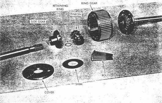
Figure 16
DISASSEMBLY
OF PARKING PAWL
Unscrew
parking pawl assembly bushing (20), remove gasket (21) and parking pawl (24).
Replace 0-rings (23 and 22) and gasket (21), if necessary. When reassembling
grease 0-rings and gaskets, torque hex bushing (20) to 40 ft. lbs.(Fig. 15
and 17). DISASSEMBLY
OF UNLOADER
VALVE BUTTON ASSEMBLY 1.
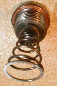
Follow step 4 of hydrostatic package removal. 2.
Remove tinnerman speed nut (4), deflector (4A), spring (5), washer (6) and
button assembly gasket (7) (Fig. 8 and 17). When
reinstalling, clean all parts thoroughly and replace button assembly gasket
and speed nut. Before placing covers on transaxle, be sure the deflector is
positioned as pictured in Figure 8, folded sides to straddle the valve caps
on hydraulic motor block. FIELD- REMOVAL AND INSTALLATION OF AXLE SEAL REMOVAL1.
Drain oil (approximately eight quarts) into clean container. 2.
Reinstall drain plug after oil has been drained. 3.
Block up tractor. 4.
Remove wheel, hub, and key. 5.
Clean area around axle and seal. |
6.
Remove paint, burrs and sharp edges. 7.
Remove axle seal with hook type tool. 8.
Clean and dry seal bore and axle. Observe condition of axle in seal lip area
and check machined seal-recess for irregularities. INSTALLATION1.
Coat inside of seal lip with lubricant. 2.
Coat outside diameter of seal with oil resistant sealer. 3.
Carefully slip seal over axle shaft towards the axle housing seal-bore. 4.
Set seal into position applying smooth uniform pressure. IMPORTANT
DO NOT
COCK OR DISTORT SEAL. CARELESSNESS COULD RESULT IN OIL LEAKAGE. 5.
Reinstall key, hub, and wheel. 6.
Remove dipstick (14) and refill with Bolens #1719650 Texamatic or automatic
transmission ATF type 'At. 7.
Reinstall dipstick. 8.
Start engine and run for at least two minutes. 9.
Recheck oil level while engine is idling. 10.
Recheck the entire hydraulic system for leaks. |
PARTS LIST
FOR HUSKY TRANSAXLE ASSEMBLY
|
REF. NO |
BOLENS PART NO. |
EATON PART NO |
DESCRIPTION |
NO.
REQ'D |
|
1 |
1106832 |
ET-94428 |
5/8
Capscrew 1/4-20 UNC x 5/8 |
3 |
|
1A |
1720287 |
ET-94428 |
3/4
Capscrew 1/4-20 UNC x 3/4 |
2 |
|
2 |
1719851 |
ETS-22630 |
Cover
Service Kit (Includes 1A, #3 and #4) |
1 |
|
3 |
1719852 |
ET-8484 |
Gasket
(Transmission Cover) |
1 |
|
4 |
1719853 |
ET-94423 |
Speed
Nut |
1 |
|
4A |
1719854 |
ET-93782 |
Deflector |
1 |
|
5 |
1719855 |
ET-94422 |
Spring |
1 |
|
6 |
1719856 |
ET-94427 |
Washer |
1 |
|
7 |
1719857 |
ET-8465 |
Gasket
(Button Assembly) |
1 |
|
8 |
1719858 |
ET-22565 |
Unloader
Button Sub-Assembly |
1 |
|
9 |
1719859 |
ET-94860 |
Oil
Filter |
1 |
|
10 |
1719860 |
ET-94853 |
Filter
Stud |
1 |
|
11 |
1720309 |
ER-8277 |
"O"
Ring (Filter Stud) |
1 |
|
12 |
1719861 |
ET-94855-2-1/2 |
Capscrew
1/2-13 UNC x 2-1/2 |
1 |
|
13 |
1719862 |
ET-94426 |
Seal
Washer (Mounting Bolt) |
1 |
|
14 |
1719863 |
ET-94893 |
Dipstick |
1 |
|
14A |
1720310 |
ER-8284 |
«O»
Ring (Dipstick) |
1 |
|
15 |
1720311 |
ER-91604 |
Drain Plug 1/4-18 NPTF |
1 |
|
16 |
1719864 |
ET-12764-2 |
Hydrostatic
- Package |
1 |
|
16A |
1721536 |
|
Hydrostatic
- Package (Tapered control shaft) |
1 |
|
17 |
1719865 |
ET-8487 |
«O»
Ring (Transmission Housing) |
1 |
|
18 |
1719866 |
ET-8369 |
«O»
Ring (Connecting Tube) |
7 |
|
19 |
1719867 |
ET-93670 |
Tube
- Connecting |
1 |